How to Wire a Junction Box When the Indicator and Load Cells are Different Brands
How to Wire a Junction Box
When the Indicator and Load Cells are Different Brands
Compare the wire functions between the two brands and identify which colors should be paired.
If wires need to be switched, it is easiest to move only the wires of the cable going to the indicator and leave the load cell wires where they are.
Examples are shown below:
Circuit Board Type
The load cell wires are placed according to the labels on the board.
Only the wires of the cable going to the indicator are switched from their original positions.
Function | +EX | -SIG | +SIG | -EX | GROUND |
| Digi-Star | RED | GREEN | WHITE | BLACK | SHIELD |
Weigh-Tronix | GREEN | RED | WHITE | BLACK | SHIELD |
The image above shows a junction box circuit board with the red and green wires going to the indicator switched. Notice that the red and green wires at the bottom of the picture do not match the labeling on the board.
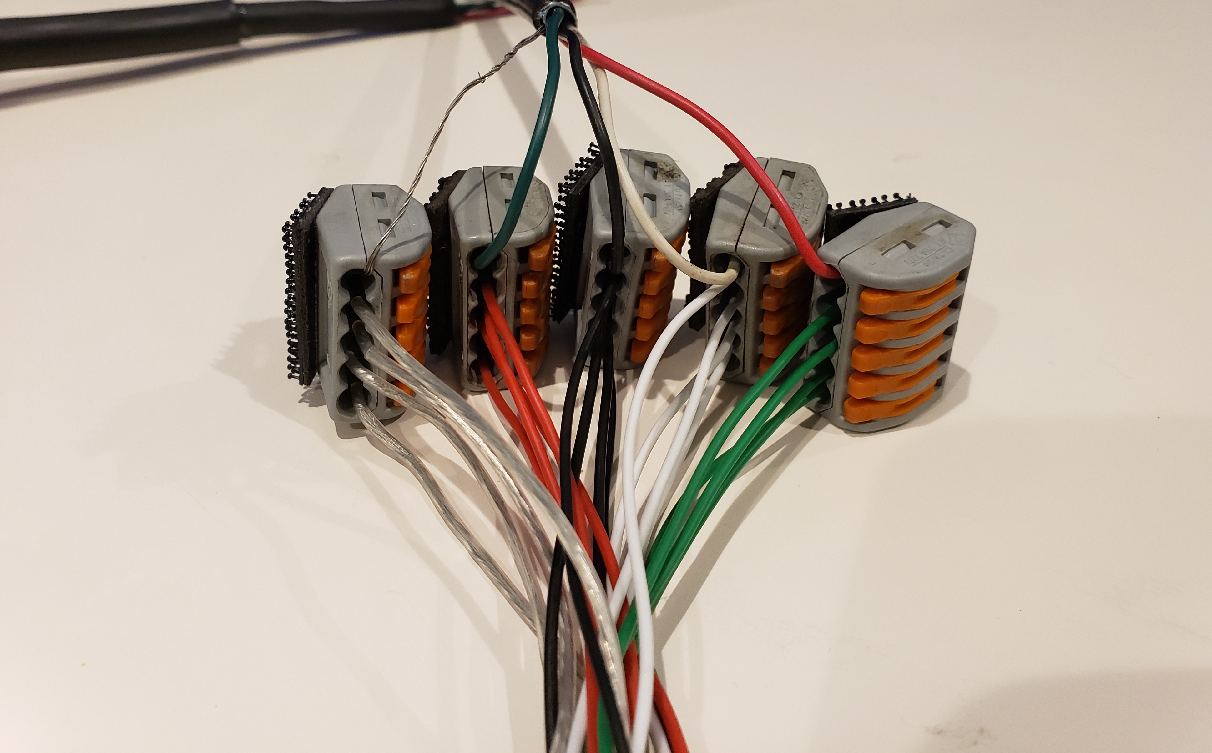
Lever Lock Type
The load cell wires are grouped together by color.
Only the wires of the cable going to the indicator will me moved from the color groupings.
Weigh-Tronix Load Cells connected to a Digi-Star Indicator
| Function | +EX | -SIG | +SIG | -EX | GROUND |
| Digi-Star | RED | GREEN | WHITE | BLACK | SHIELD |
| Weigh-Tronix | GREEN | RED | WHITE | BLACK | SHIELD |
Using the same example, the functions of the red and green wires are switched between the two brands. In order for the scale to work correctly the wire positions must be changed.
The image above shows a set of junction box lever locks with the red and green wires going to the indicator switched. Notice that the red and green wires at the top of the picture do not match the other wires they are grouped with.
Related Articles
7601400 - Junction Bank Manual Rev A
Congratulations on the purchase of your new Scale-Tec DT06 Junction Bank. This Junction bank is designed to provide superior connection keeping dust and moisture out of the connection, as well as provide easy serviceability for troubleshooting ...DT6 Junction Bank Overview
We recommend routing your load cell and weigh bar connections through the DT6 junction bank, which comes standard with all of our scale kits. Bare wire connections and damaged or weathered junction boxes are common trouble areas in a scale system. A ...Load Cell Wire Functions
Load Cell Wire Functions Function +EX -SIG +SIG -EX GROUND Digi-Star, RAVEN, Reliable RED GREEN WHITE BLACK TRANSPARENT Weigh-Tronics GREEN RED WHITE BLACK ORANGE Dinamica Generale, Eaton, Rice Lake, Rinstrum, Trans Cell, G-ELDER, Intercomp, Te Pari ...Wiring Quarter Bridge Load Cells in a Lever-Lock Junction Box
Eaton Function J-Box Cable (DS) Load Cell 1 Load Cell 2 Load Cell 3 Load Cell 4 +Sig White White White -Sig Green White White +Ex Red Black Red Black Red -Ex Black Red Black Red Black Shield Shield Green Green Green Green AWT 4-Pin Function J-Box ...Crown 4-Pin Load Cell Cable
CROWN 4-PIN CONNECTOR WIRE ILLUSTRATION PIN COLOR A WIRE BRAID B RED C BLACK D WHITE NOTE: 4 PIN Load Cells/Weigh-Bars can not be intermixed with 5-PIN Load Cells. They can, however, be summed together at a junction box and utilized with a 5 PIN ...